Koyo Technical Information
9. Lubrication
a. Grease lubrication
1) Grease lubrication
Grease is made by mixing and dispersing a solid of high oil-affinity (called a thickener) with lubricant oil (as a base), and transforming it into a semi-solid state.
As well, a variety of additives can be added to improve specific performance.
- Base oil
Mineral oil is usually used as the base oil for grease. When low temperature fluidity, high temperature stability, or other special performance is required, diester oil, silicon oil, polyglycolic oil, fluorinated oil, or other synthetic oil is often used.
Generally, grease with low viscosity base oil is suitable for applications at low temperature or high speed; grease with high viscosity base oils is suitable for applications at high temperature or under heavy load. - Thickener
Thickeners are an important factor to determine grease performance. Table 9-1 shows the properties of common thickeners.
Table 9-1 Characteristics of thickeners
| Thickener | Operating temperature range °C | Rotational speed range | Mechanical stability | Water resistance | Pressure resistance |
|---|---|---|---|---|---|
| Lithium soap | -30 to 120 | Medium to high | Excellent | Good | Good |
| Calcium soap | -10 to 70 | Low to medium | Fair to good | Good | Fair |
| Sodium soap | 0 to 110 | Low to high | Good to excellent | Bad | Good to excellent |
| Urea compounds | -30 to 150 | Low to high | Good to excellent | Good to excellent | Good to excellent |
| Bentone | -10 to 150 | Medium to high | Good | Good | Good to excellent |
| Fluorine compounds | -40 to 250 | Low to medium | Good | Good | Good |
- Additives
Major additives and their uses are as follows:
Extreme pressure agents -> When bearings must tolerate heavy or impact loads.
Oxidation inhibitors -> When grease is not refilled for a long period.
2) Amount of grease
Generally, grease should be supplied into the housing such that one third or half of the internal space is filled, though the grease amount should be adjusted according to the housing construction and the size of internal space.
When the grease amount is excessive, it may be heated up by agitation and changing the properties of deteriorating or softening, grease.
If the bearing is used at a low speed, the space may be filled up to two thirds or entirely to prevent ingress of foreign matter.
3) Grease feeding interval, grease life
- Grease feeding interval
The service life of grease enclosed in the housing can be determined from Fig. 9-1.Add or replace grease before the end of the service life determined from Fig. 9-1.If a reduced amount of grease is initially enclosed to accommodate high speed, remove old grease to the extent that fresh grease is added.To determine regreasing interval, use the Menu entitled Grease Feeding Interval.Fig.9-1 Grease feeding interval
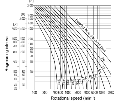
[A] : radial ball bearings
[B] : cylindrical roller bearings, needle roller bearings
[C] : tapered roller bearings, spherical roller bearings, thrust ball bearings
Temperature correction
When the bearing operating temperature exceeds 70°C, obtained by multiplying tf by correction factor a, found on the scale below, should be applied as the feeding interval.
tf‘=tf×aTemperature correction factor a

Bearing operating temperature °C
Example of calculating grease feeding interval:
In case of a tapered roller bearings with a bore diameter of 100 mm and running speed of 300 min-1, grease has a service life of approximately 8,500 hours, as indicated in Fig. 9-1.
If the amount of grease initially enclosed is 0.4 kg, it decreases 0.00113 kg a day (0.4 kg × 24 h / 8,500 h = 0.00113 kg/day).
If grease is fed once a week, the total grease to be added is 0.008 kg (0.00113 × 7 days = 0.008 kg).
- Grease life in shielded/sealed ball bearing
The service life of grease enclosed in single-row deep-groove ball bearings, closed with a seal or a shield, can be estimated by the equation below.
To determine accurate grease service life, use the Menu entitled Grease Life of Shielded/Sealed Ball Bearings.
logL= 6.10-4.40 × 10⁻⁶dmn-2.50 (Pr / Cr-0.05) – (0.021-1.80 × 10⁻⁸dmn) T
| where: | ||
| L : | grease life | h |
| dm : | (D + d) / 2 (D : bearing outside diameter, d : bearing bore diameter) | mm |
| n : | rotational speed | min-1 |
| Pr : | dynamic equivalent radial load | N |
| Cr : | basic dynamic radial load rating | N |
| T : | operating temperature of bearing | °C |
The conditions for applying equation are as follows. When other conditions are applied, Koyo should be consulted.
- Operating temperature of bearing : T°C
Applicable when T ≤ 120
50 ;
- Value of dmn
Applicable when dmn ≤ 500,000
when dmn < 125,000 ; dmn=125,000
- Load condition: Pr / Cr
Applicable when Pr/Cr ≤ 0.2
when Pr/Cr < 0.05 ; Pr/Cr=0.05
b. Oil lubrication
b.1. Lubricating oil
For lubrication, bearings usually employ highly refined mineral oils, which have superior oxidation stability, rust-preventive effect, and high film strength. With bearing diversification, however, various synthetic oils have been put into use.
Characteristics of lubricating oils
| Type of lubricating oil | Highly refined mineral oil | Major synthetic oils | ||||
|---|---|---|---|---|---|---|
| Diester oil | Silicon oil | Polyglycolic oil | Polyphenyl ether oil | Fluorinated oil | ||
| Operating temperature range (°C) | -40 to +220 | -55 to +150 | -70 to +350 | -30 to +150 | 0 to +330 | -20 to +300 |
| Lubricity | Excellent | Excellent | Fair | Good | Good | Excellent |
| Oxidation stability | Good | Good | Fair | Fair | Excellent | Excellent |
| Radioactivity resistance | Bad | Bad | Bad to fair | Bad | Excellent | – |
Selection of lubricating oil
When lubricating oil viscosity is too low, the oil film will be insufficient. On the other hand, when the viscosity is too high, heat will be generated due to viscous resistance.
In general, the heavier the load and the higher the operating temperature, the higher the lubricating oil viscosity should be; whereas, the higher the rotation speed, the lower the viscosity should be.
Proper kinematic viscosity can be obtained through selection by bearing type according to the following table.
Table 9-2 shows the relationship between lubricating oil viscosity and temperature.
Proper kinematic viscosity by bearing type
| Bearing type | Proper kinematic viscosity at operating temperature |
|---|---|
| Ball bearing Cylindrical roller bearing |
13mm2/s or higher |
| Tapered roller bearing Spherical roller bearing |
20mm2/s or higher |
| Spherical thrust roller bearing | 32mm2/s or higher |
b.2. Kinematic viscosity
Table 9-2 Proper kinematic viscosities by bearing operating conditions
| Operating temperature | dmn value | Proper kinematic viscosity (expressed in the ISO viscosity grade or the SAE No.) | |||
|---|---|---|---|---|---|
| Light/normal load | Heavy/impact load | ||||
| -30 to 0°C | All rotation speeds | ISO VG 15, 22, 46 | (Refrigerating machine oil) | – | |
| 0 to 60°C | up to 300 000 | ISO VG 46 | Bearing oil Turbine oil |
ISO VG 68 SAE 30 |
Bearing oil Turbine oil |
| 300 000 to 600 000 |
ISO VG 32 | Bearing oil Turbine oil |
ISO VG 68 | Bearing oil Turbine oil |
|
| over 600 000 | ISO VG 7, 10, 22 | Bearing oil | – | ||
| 60 to 100°C | up to 300 000 | ISO VG 68 | Bearing oil | ISO VG 68, 100 SAE 30 |
Bearing oil |
| 300 000 to 600 000 |
ISO VG 32, 46 | Bearing oil Turbine oil |
ISO VG 68 | Bearing oil Turbine oil |
|
| over 600 000 | ISO VG 22, 32, 46 | Bearing oil Turbine oil Machine oil |
– | ||
| 100 to 150°C | up to 300 000 | ISO VG 68, 100 SAE 30, 40 |
Bearing oil | ISO VG 100 ~ 460 | Bearing oil Gear oil |
| 300 000 to 600 000 |
ISO VG 68 SAE 30 |
Bearing oil Turbine oil |
ISO VG 68, 100 SAE 30, 40 |
Bearing oil | |
[Remarks]
1. dmn = (D + d) / 2 × n ![]()
![]()
![]() { D : bearing outside diameter (mm) , d : bearing bore diameter (mm) , n : rotational speed (min-1) }
{ D : bearing outside diameter (mm) , d : bearing bore diameter (mm) , n : rotational speed (min-1) }
2. Refer to refrigerating machine oil (JIS K 2211), turbine oil (JIS K 2213), gear oil (JIS K 2219), machine oil (JIS K 2238) and bearing oil (JIS K 2239).
3. Contact Koyo if the bearing operating temperature is under -30°C or over 150°C.
b.3. Lubrication methods
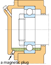
1) Oil bath
- Simplest method of bearing immersion in oil for operation.
- Suitable for low/medium rotation speed.
- Oil level gauge should be furnished to adjust the amount of oil.
(In the case of horizontal shaft) About 50% of the lowest rolling element should be immersed.
(In the case of vertical shaft) About 70 to 80% of the bearing should be immersed. - It is better to use a magnetic plug to prevent wear iron particles from dispersing in oil.
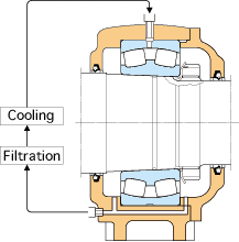
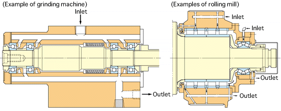
2) Forced oil circulation
- This method employs a circulation-type oil supply system.
Supplied oil lubricates inside of the bearing, is cooled and sent back to the tank through an oil escape pipe. The oil, after filtering and cooling, is pumped back. - Widely used at high rotation speeds and high temperature conditions.
- It is better to use an oil escape pipe approximately twice as thick as the oil supply pipe in order to prevent too much lubricant from gathering in housing.
Required oil supply in forced oil circulation and oil jet lubrication
|
G =
|
1.88 × 10⁻⁴ µ ⋅ d ⋅ n ⋅ P |
| 60 c ⋅ r ⋅ ∆T |
| where | ||
|
G
|
: required oil supply | L / min |
|
µ
|
: friction coefficient (see table at right) | |
|
d
|
: bearing bore diameter | mm |
|
n
|
: rotation speed | min-1 |
|
P
|
: dynamic equivalent load of bearing | N |
|
c
|
: specific heat of oil, 1.88 to 2.09 | kJ/kg⋅K |
|
r
|
: density of oil | g/cm3 |
|
∆T
|
: temperature rise of oil | K |
Values of friction coefficient µ
| Bearing type | µ |
|---|---|
| Deep groove ball bearings Angular contact ball bearings Cylindrical roller bearings Tapered roller bearings Spherical roller bearings |
0.0010 to 0.0015 0.0012 to 0.0020 0.0008 to 0.0012 0.0017 to 0.0025 0.0020 to 0.0025 |
The values obtained by the above equation show amount of oil required to carry away all the generated heat, with heat release not taken into consideration. In reality, the oil supplied is generally half to two-thirds of the calculated value. Heat release varies widely according to the application and operating conditions.
To determine the optimum oil supply, it is advised to start operating with two-thirds of the calculated value, and then reduce the oil gradually while measuring the operating temperature of bearing, as well as the supplied and discharged oil.
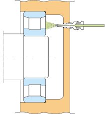
3) Oil jet lubrication
- This method uses a nozzle to jet oil at a constant pressure (10 to 50N/cm2), and is highly effective in cooling.
- Suitable for high rotation speed and heavy load.
- Generally, the nozzle (diameter 0.5 to 2 mm) is located 5 to 10 mm from the side of a bearing. When a large amount of heat is generated, 2 to 4 nozzles should be used.
- Since a large amount of oil is supplied in the jet lubrication method, old oil should be discharged with an oil pump to prevent excessive residual oil.
- Required amount of oil: see reference
4) Oil mist lubrication (spray lubrication)
- This method employs an oil mist generator to produce dry mist (air containing oil in the form of mist). The dry mist is continuously sent to the oil supplier, where the mist is turned into a wet mist (sticky oil drops) by a nozzle set up on the housing or bearing, and is then sprayed onto bearing.
- This method provides and sustains the smallest amount of oil film necessary for lubrication, and has the advantages of preventing oil contamination, simplifying bearing maintenance, prolonging bearing fatigue life, reducing oil consumption etc.
– Required amount of mist (mist pressure: 500mm in water column)
| (In the case of a bearing) | Q =0.11dR |
| (In the case of two oil seals combined) | Q =0.0028d1 |
| where: | ||
| Q : | required amount of mist | L/min |
| d : | bearing bore diameter | mm |
| R : | row numbers of bearing | |
| d1 : | inside diameter of oil seal | mm |
In the case of high speed rotation (dmn ≤ 400,000), it is necessary to increase the amount of oil and heighten the mist pressure.
– Piping diameter and design of lubrication hole/groove
When the flow rate of mist in piping exceeds 5m/s, oil mist suddenly condenses into an oil liquid.
Consequently, the piping diameter and dimensions of the lubrication hole/groove in the housing should be designed to keep the flow rate of mist, obtained by the following equation, from exceeding 5m/s.
| V = | 0.167Q | ≤5 |
| A |
| where : | ||
| V | : flow speed of mist | m/s |
| Q | : amount of mist | L/min |
| A | : sectional area of piping or lubrication groove | cm2 |
– Mist oil
Oil used in oil mist lubrication should meet the following requirements.
- Ability to turn into mist
- Has high extreme pressure resistance
- Good heat/oxidation stability
- Rust-resistant
- Unlikely to generate sludge
- Superior demulsifier
Oil mist lubrication has a number of advantages for high speed rotation bearings. Its performance, however, is largely affected by surrounding structures and bearing operating conditions. If contemplating the use of this method, please contact Koyo for advice based on our long experience with oil mist lubrication.
5) Oil/air lubrication
- A proportioning pump sends forth a small quantity of oil, which is mixed with compressed air by a mixing valve.
The admixture is supplied continuously and stably to the bearing. - This method enables quantitative control of oil in extremely small amounts, always supplying new lubricating oil.
It is thus suitable for machine tools and other applications requiring high rotational speed. - Compressed air and lubricating oil are supplied to the spindle, increasing the internal pressure and helping prevent dirt, cutting-liquid, etc. from entering.
As well, this method allows the lubricating oil to flow through a feeding pipe, minimizing atmospheric pollution.
(Example of spindle unit incorporating oil/air lubrication system)

- Koyo produces an oil/air lubricator and, air cleaner, as well as a spindle unit incorporating the oil/air lubrication system.

 Exclusive North American distributor for Gamet Bearing.